Understand CSV Files
|
This page includes info on CSV Files. |
Directory
|
This page includes info on CSV Files. |
About CSV FilesCSV FILES are created from Google drive in this form:
|
Features(Needs Google Account to access features)
|
Quadstick conjunction with CSV FILES
|
What's Next?Once having grasp on information involving CSV Files, head over to Create CSV Files page to further experience control over Quadstick files.... |
Overview
To better understand CSV Files, Default.csv will be used as an example.
(Watch video or continue reading page for info)
- (Top)---(Same Section)
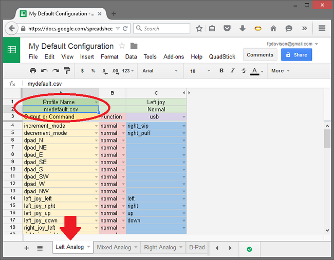
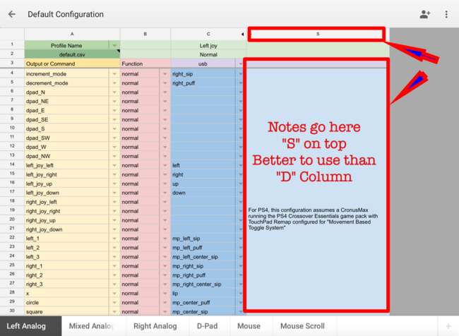
1. This is the Default.csv file and the Red oval is the title of sheet. Can be Changed just leave.csv
- (Top)---(Same Section)
2. Red Arrow dictates the mode/sheet currently on. There my be multiple modes/sheets
- (Top)---(Same Section)
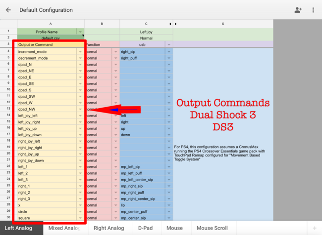
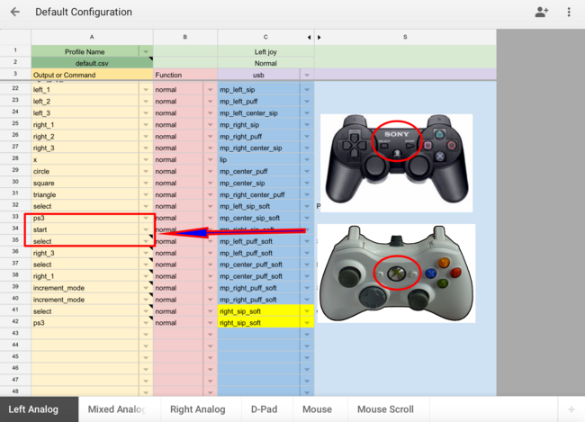
3. Yellow Left column is the output command that Quadstick will perform . It is set as Dualshock 3 (DS3 aka PS3); Xbox and PlayStation buttons are remotely identical.
- (Top)---(Same Section)
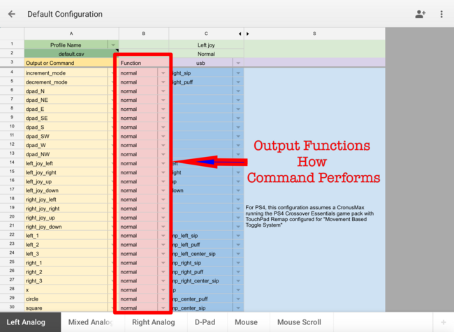
4. Red column is the Function command that tells Quadstick how it will perform the Action/button.
- (Top)---(Same Section)
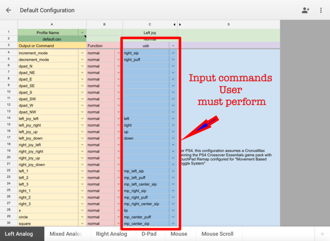
5. Third Blue column is the USB/Input command that is the Quadstik button location that the User must perform in order to trigger selected output command
- (Top)---(Same Section)
6. S column sometimes D is used for notes, to help Users remember the actions of buttons.
- (Top)
Step-by-Step
As stated on Overview, the Yellow Left column is the output command that Quadstick will perform . It is set as Dualshock 3 (DS3 aka PS3); Xbox and PlayStation buttons are remotely identical.
So let's go down the list, but note the example will be demonstrating PS3 controls since this is DS3...that being said, Xbox/PS are identical just different button names .
Ex): Xbox same as PlayStation >>> LT same as L2 ~-~ B same as O ~-~ A same as X
Ok let's get started...
- (Top)---(Same Section)
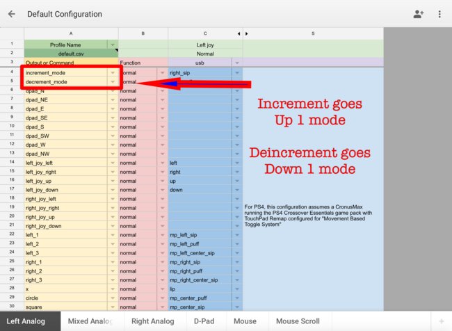
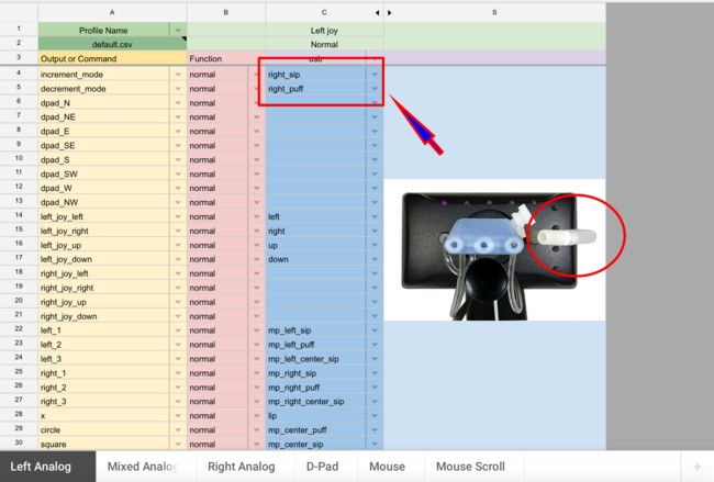
1.Increment mode = goes up one mode, while Deincrement mode goes down one mode.
- (Top)---(Same Section)
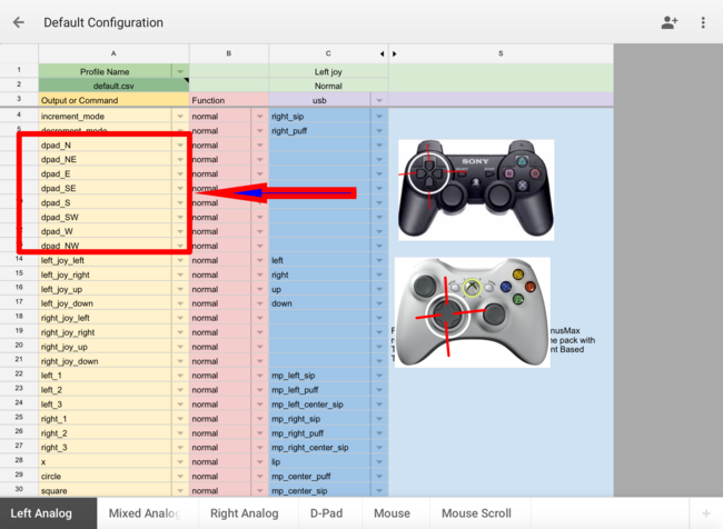
2.Next 6 sections involve D-pad (N,E,S,W are most important.
- (Top)---(Same Section)
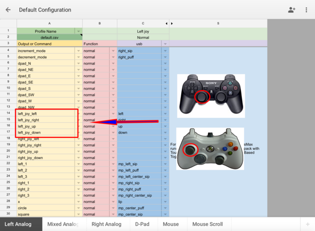
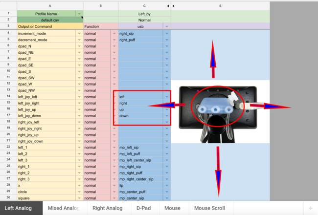
3.This section outputs Left Analog.
- (Top)---(Same Section)
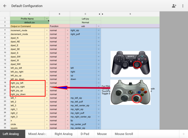
4. While This section outputs Right Analog.
- (Top)---(Same Section)
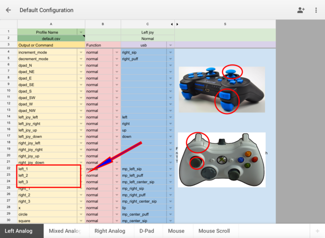
5.These 3 control L1/L2/L3(Left stick press).
- (Top)---(Same Section)
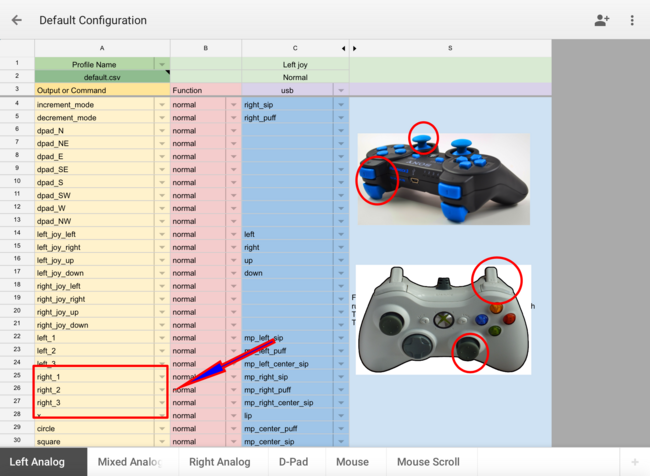
6. While These 3 control R1/R2/R3(Right Stick press).
- (Top)---(Same Section)
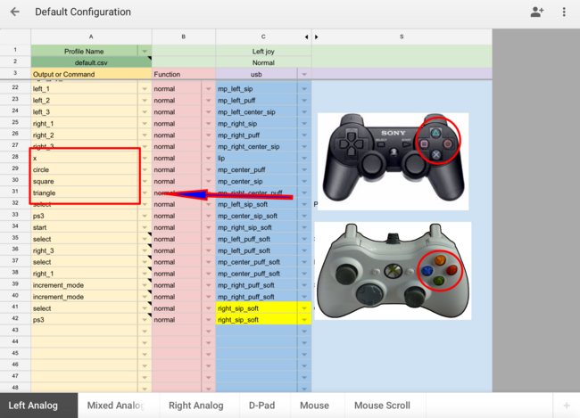
7.Main 4 Buttons are reprinted below X/Circle/Square/Triangle same as A/B/X/Y.
- (Top)---(Same Section)
8.Finally the Last 3 are Home Button/Select/Start.
Red Column: Output Function
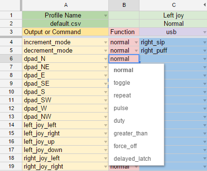
The response of an Output to its active Input can be controlled by selecting the output Function from the following list:
normal
The output is active only when the input is active.
toggle
When the input activates, the output will toggle, or latch, its on/off state. It will hold its last on/off state until the next input activation or if the user changes to a mode that does not have the output configured with a toggle.
repeat
As long as the input is active, the output will turn on and off repeatedly. The default rate is 10 times per second. An optional value for the number of repeats per second may be placed in the cell after the word, like "repeat 4". Adding a number after the word repeat will cause a red validation error marker, which can be ignored.
pulse
When the input goes from inactive to active, the output will turn on for brief period of time. The default is 100ms. An optional parameter for the duration of the pulse, in milliseconds, may be placed in the cell after the word, like "pulse 1500". Ignore the red validation marker when using the optional parameter.
(Vid down below)
delayed_off
delay_off is a lot like pulse, except the time delay starts at the end of the input activation instead of the beginning. If you hold the input on for a while, then release it, you should see the delay. If you just do a quick sip and release, it will work just like the pulse function.
[An optional parameter for the duration of delayed off, in milliseconds, may be placed in the cell after the word, like "delayed _off 1500". Ignore the red validation marker when using the optional parameter]
duty
As the input value goes from 0 to 100%, scale the duration of the on-time of the output. The default minimum on/off time is 100ms. An optional parameter, in milliseconds, can be added to adjust the minimum on/off time. Ignore the red validation marker when using the optional parameter.
greater_than
When the analog value of the input equals or exceeds a value, the output will turn on. (So this function is actually misnamed) The default value is 100%, which will turn on the output when the input reaches 100%. (A normal function turns on at 1%). An optional parameter, in percent, may be added. Ignore the red validation marker when using the optional parameter.
[An optional parameter for the duration of greater than, in milliseconds, may be placed in the cell after the word, like "greater_than 1500". Ignore the red validation marker when using the optional parameter]
(Vid down below)
less_than
When the analog value of the input equals or exceeds a value, the output will turn off. (So this function is actually misnamed) The default value is 1%, which will turn off the output when the input reaches 1%. (A normal function turns on at 1%). An optional parameter, in percent, may be added. Ignore the red validation marker when using the optional parameter.
Basically, this function lets the command continue to stay ON until sufficient amount of pressure is given, but once applied pressure is released..it turns back on again
Max value that can ba applied is 100%
[An optional parameter for the duration of less than, in milliseconds, may be placed in the cell after the word, like "less_than 1500". Ignore the red validation marker when using the optional parameter]
force_off
When the input activates, it will force the output off. This is used to allow one input to force off an output that was turned on by an earlier input.
Force Off works with a delay parameter. If you don't add one, the default delay is 1 ms. At the end of the delay, it clears the specific command assigned to off . It both clears the value to 0 and the toggle/delayed latch, so it is ready for the next activation.
Force Off should work with latching type functions (toggle, delay_latch, delay_off, pulse). Not with greater_than, less_than, constant.
[An optional parameter for the duration of force off, in milliseconds, may be placed in the cell after the word, like "force_off 1500". Ignore the red validation marker when using the optional parameter]
delayed_latch
When the input activates, the output will activate. If the input is held active for longer than a period of time, the output will latch on and stay on when the input deactivates. If the input is held active for less than the time period, the output will deactivate when the input deactivates. A previously latched output can be turned off with a brief activation of the input or forced off by another input. The default delay period is 1000ms.
[An optional parameter for the duration of the delayed latch, in milliseconds, may be placed in the cell after the word, like "delayed_latch 1500". Ignore the red validation marker when using the optional parameter]
(Vid down below)
constant
"constant" will be in the Inputs dropdown list, not with the functions. It just holds the associated output on constantly, like an input that is constantly on.
When you're put Constant as input command, The output command stays automatically on and will NEVER turn off while you're within the mode that it is applied to.
As stated on Overview, the Blue column is the Quadstik button location That the User must perform in order to trigger selected output command.
Ok let's get started... You may watch video below or continue reading.
(Important)
- mp= Mouth piece
- This is how the blue column translate:
(mp_right_sip >> mp_Location_Action)
(mp_right_center_sip >> mp_Location_Location_Action)
(mp_right_center_sip_soft >> mp_Location_Location_Action_ActionPerformed)
- (Top)---(Same Section)
1.
- Red = right sip/puff which is located on the side of the Quadstick & this combination triggerd by sip/puff only that hole.
- (Top)---(Same Section)
2. Moving the mouth stick will trigger the Direction of Left/Right/Up/Down.
- (Top)---(Same Section)
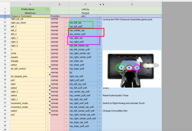
3.
- Green = mp left sip/puff which is located on left hole on Quadstick & this combination triggerd by sip/puff only that hole.
- Red = mp center sip/puff which is located on middle hole on Quadstick & this combination triggerd by sip/puff only that hole.
- Pink = mp right sip/puff which is located on right hole on Quadstick & this combination triggerd by sip/puff only that hole.
- (Top)---(Same Section)
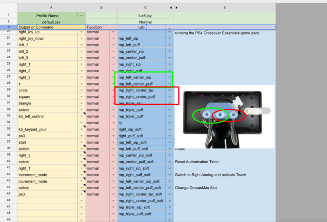
4.
- Green = mp left center sip/puff which is located on left & middle hole on Quadstick & this combination triggerd by sip/puff both holes at the Same time.
- Red = mp right center sip/puff which is located on right & middle hole on Quadstick & this combination triggerd by sip/puff both holes at the Same time.
- (Top)---(Same Section)
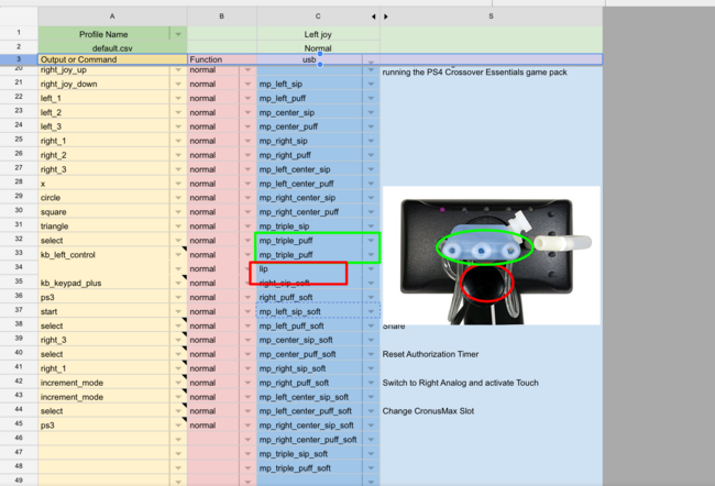
5.
- Green = mp triple sip/puff which is located on all 3 holes on Quadstick & this combination triggerd by sip/puff all 3 holes at the Same time.
- Red = Lip which is located on Lip sensor on Quadstick & this combination triggerd by pushing Lip sensor only .
- (Top)---(Same Section)
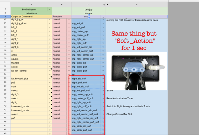
6. the picture down below is essentially the same as everything covered in this section, but you perform the action of sip/puff softly for 1 sec


